Introduction
Welcome to N4 Flight software docs. N4 Flight software is the code used to run N4 rockets at Nakuja Rocket Project. This code is built using FreeRTOS on the Arduino-ESP32 framework. It is designed to run either on AI-Thinker NodeMCU-ESP32 boards or ESP32-DOIT-DEVKIT V1.
Major features
This firmare has been improved tremendously from the previous versions and includes the following features:
Modularity
- Most of the code is now contained in separate files each perfoming its own singular task to ensure code maintainability and testing.
System Logging
- We have built a system logger to keep track of each and every operation that the flight computer undertakes. This can be be retrieved later and reviewed for post-flight analysis
HIL Testing Engine
- A hardware-in-the-loop testing engine has been built into the flight software to allow us to "Test Like We Fly". This allows the flight computer to be tested and debugged way before flight day. Using an improvised XMODEM algorithm, we are able to upload test flight data and run necessary integration tests.
- Note
- See Integration and Testing Procedures for more info
Flight data logging
- Flight data logging has been improved. Using an onboard SPI Flash memory, we are able log sensor data and flight states.
Data dump interface
- A data dumping hardware interface has been added to ease the retrieval of data post flight data.
SAFE and ARMED modes
- To prevent misfires during integration and testing, this firmware implements SAFE_MODE that among others operations, disables the pyro-charges before ARMING is done.
XBEE, MQTT, LORA, WIFI telemetry selection
- For backward and forward compatibility, we implement a method to allow choice of data telemetry protocol being used.
Double ejection
- We implement drogue and main chute ejection algorithms for successful vehicle recovery
Building, Compilation and Downloading.
System requirements
The following must be installed to build this release:
- PlatformIO Core. Download the core here: PlatformIO Core
- PlatformIO IDE (recommended on VS Code but you can use IDE of your choice). To install PlatformIO IDE, follow the steps listed here: PlatformIO IDE
- Serial Monitor tool e.g. Putty, Ai-Thinker Serial, RealTerm etc
Building the code
- Clone the repo on your local machine
git clone https://github.com/nakujaproject/N4-Flight-Software.git
- Note
- You can also download the folder as a zip file and extract it to a folder of your choice. But we recommend cloning it so you can keep up to date with the remote changes.
- Change the directory to
N4-Flight-Software\n4-flight-software
- Install code dependencies
- Build
- Connect your flight computer using a USB cable and make sure it is seen by your PC. It should be listed under Device Manager>Ports, if you are on windows
- Note
- If your ESP32 is note recognized, you have to install USB-TO-TTL chip driver manually. For ESP32 Boards using CH340 chip, download the driver here CH340 Driver-SparkFun. Run the driver and it will be automatically installed on your machine. For ESP32 Boards using CP2102 chip, follow the procedure here CP2102-driver-POLOLU. Run the driver and it will be automatically installed on your machine.
Upload and run Close any open serial ports connected to that ESP32 and run the command below
The firmware will be uploaded to the flight computer!
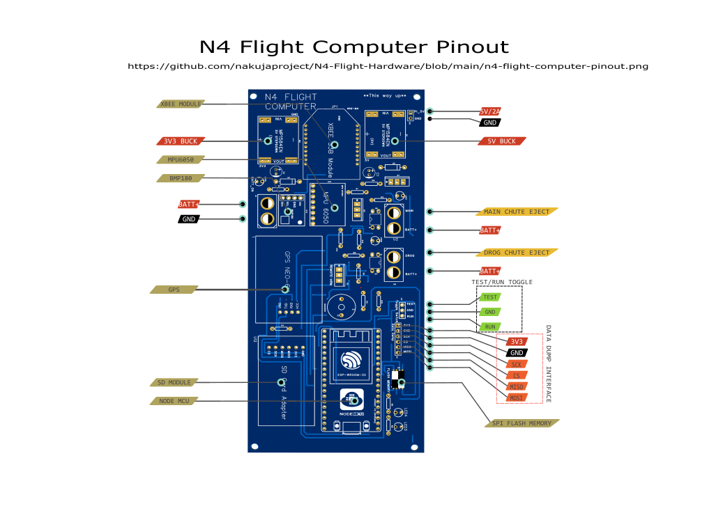
Hardware, pin assignment and peripherals
The pin assignment to ESP32 are listed in the following file: https://github.com/nakujaproject/N4-Flight-Software/blob/main/flight-computer-pin-assignment-version-1.xlsx
Pre-flight software checks
The following checks MUST be performed pre-flight to ensure the software operates as designed:
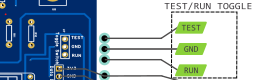
The flight computer MUST be in the RUN mode during launch. RUN mode is set by setting the toggle pin on the side labelled as RUN
- Telemetry protocol selection (MQTT or XBEE)
If using MQTT with WIFI, ensure that the #define MQTT in defs.h is set to 1. If using XBEE, ensure that the #define #define XBEE in defs.h is set to 1. If using both, enure both are set to 1.
Ideally, every rocket is named before launch. So change the rocket_ID variable in main.cpp before uploading the code to a specific flight computer. This naming will help with the log files to know which data belongs to which computer.
In SAFE MODE, The green LED on the flight computer should be blinking, the red LED should be OFF. In ARMED MODE, the red LED should be blinking, the green LED should be OFF. Do not connect the pyro-technic charges while the flight computer is in ARMED MODE. Arming is done only from the base station, away from the rocket to prevent any misfires.
Debug via the serial monitor should be enabled only on ground during development and testing. During flight, debugging to terminal should be disabled. To disable debugging, set the DEBUG and DEBUG_TO_TERMINAL constants in defs.h to 0.
During development, it is discovered that logging to memory every time is a waste of memory resources, which are scarce. Log to memory only when needed. Set the LOG_TO_MEMORY constant in defs.h to 0 to disable logging to memory and set to 1 to enable. This variable MUST be set to 1 during flight, otherwise there will be no data collected.
WIFI network configuration
The software is written such that it allows connection to any WIFI being used, without hardcoding the WIFI credentials into the flight software. This will make the launch preparation faster as no code uploading needs to be done on-site. Follow the procedure below to connect to WIFI:
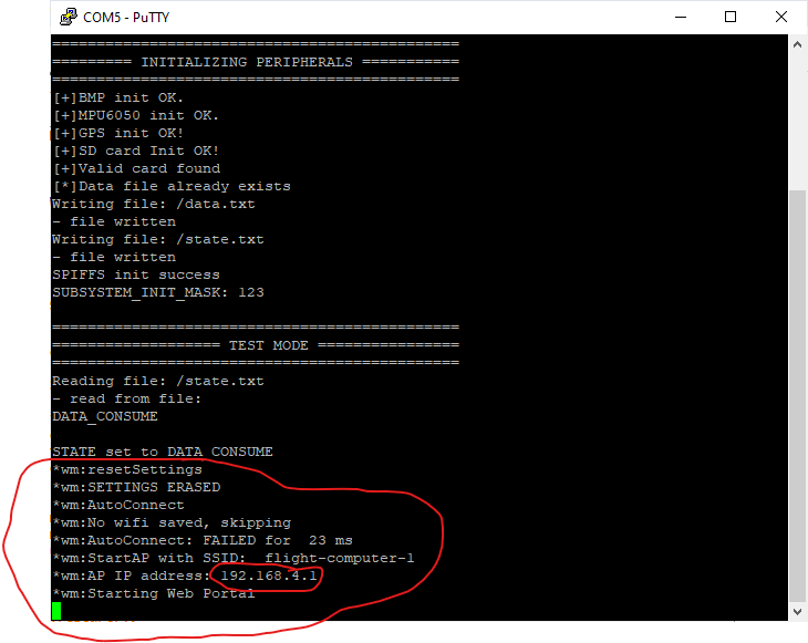
- After uploading the flight software to the computer, the serial terminal will show the following response. Note the marked are which is of interest.
This shows that the flight computer has created a web portal and is waiting for connection from an external device.
- When powered on, the flight computer will create an open WIFI network called "flight-computer-1". This network will be visible on any device within range.
- The FC sets itself as an Access Point and will provide its own WIFI network to the for other devices to connect to.
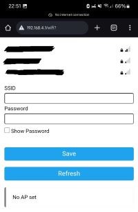
- On the ground station computer, or using a smartphone, connect to "flight-computer-1". (NOTE: The WIFI name will change depending on the name of the rocket being used )
- Open the browser and go to the following IP address "192.168.4.1". This should open the following window in your browser.
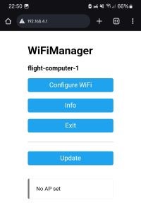
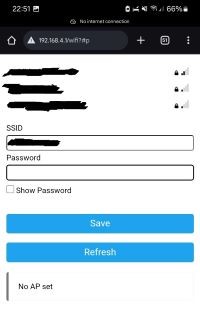
Click on Configure WiFi. The window below opens.
- Enter the WIFI SSID and password for the network you want to connect to. In this case it is the WIFI network used for telemetry transmission.
- Press save. The flight computer will save the network credentials and auto-reconnect itself as a station to the launch WIFI network.
– Assuming that the you have supplied the correct login credentials, the ESP32 will now be connected to the WiFi network.
- You can now stream telemetry over that network.
- Make sure that the ground station PC and the flight computer are on the same network.
MQTT configuration
- Note
- In Development
Flight Data Collection and Kalman Filtering
The main senors used in the flight computer are accelerometer and pressure sensors. We use the MPU6050 for acceleration and angular velocity measurements. We use the BMP180 for atmospheric pressure and altitude measurement. This data is collected as raw data which is then processed and filtered using the Kalman filter algorithm.
The Kalman Filter allows us to perform predictive recursive low pass filtering which greatly improves our collected sensor data which is safe for the state machine to consume.
To learn more about the Kalman filter implementation, refer to the kalman.h and kalman.cpp files in the src folder of the n4-flight-software.
Launch detection
Launch is detected using the altimeter data. There is a set threshold above which a rocket is considered to be launched. This variable is in the LAUNCH_DETECTION_THRESHOLD in defs.h. If the onboard altimeter registers that the current relative altitude is above this threshold, then the rocket is considered as launched.
If the flight computer is not armed when launch is detected, it is automatically armed to override the arming command from base station.
Apogee detection
We detect apogee using relative altitude values from the altimeter. The logic we use is that the * rocket's altitude increases as it ascends up continuously. On reaching apogee, the rocket's altitude *starts decreasing.
To detect the decrease in altitude, we keep track of the last SIZE_OF_BUFFER items (see *ring_buffer.h). We then check the current altitude value against the oldest value in the ring *buffer. If the difference is more than the set THRESHOLD (usually 5 meters), we are sure that at *this point the rocket is coming down and we register APOGEE.
This is made possible using a ring buffer(circular buffer), that is implemented to always keep track of the previous SIZE_OF_BUFFER. From this buffer we can infer apogee.
Parachute ejection
This version of the flight software implements double ejection mechanism. ... [TODO]
Flight data logging and data recovery
Flight data is logged in the external SPI flash memory. The file used is called flight.txt. The contents of the flight.txt are erased during setup of the fight computer. Logging starts after the flight computer has been armed, to prevent logging unnecesary pre-flight data.
First make sure you have the following serial tool downloaded:
Ai Thinker Serial port debugging assistant
To recover the file, follow the procedure below to get the data dumped from the flight computer.
- After the rocket has landed, disconnect the computer from the battery in the avionics bay.
- Assuming the onboard ESP32 is not damaged, connect via USB cable and upload the code in \flight-data-recovery\n4-data-recovery-code folder, using the command below:
- After the code has uploaded, open the Ai-THINKER serial monitor tool downloaded above.
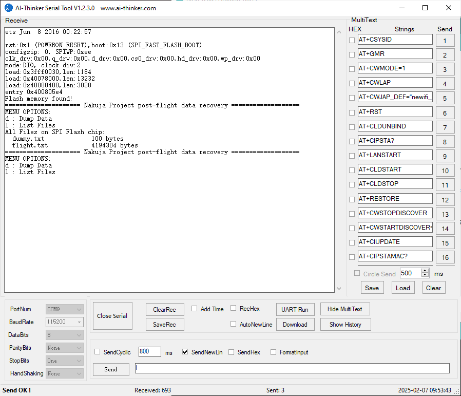
- Press RESET (EN) on the onboad ESP32. The following window should open:
This file shows the options you are provided with after running the software. The options are described below:
- List files - List all the files saved in the flash memory
- Dump data - dump all the data in the flight.txt file.
- To select an option, enter the letter shown on the option and press SEND. The corresponding action will occur. For example l to select List all files
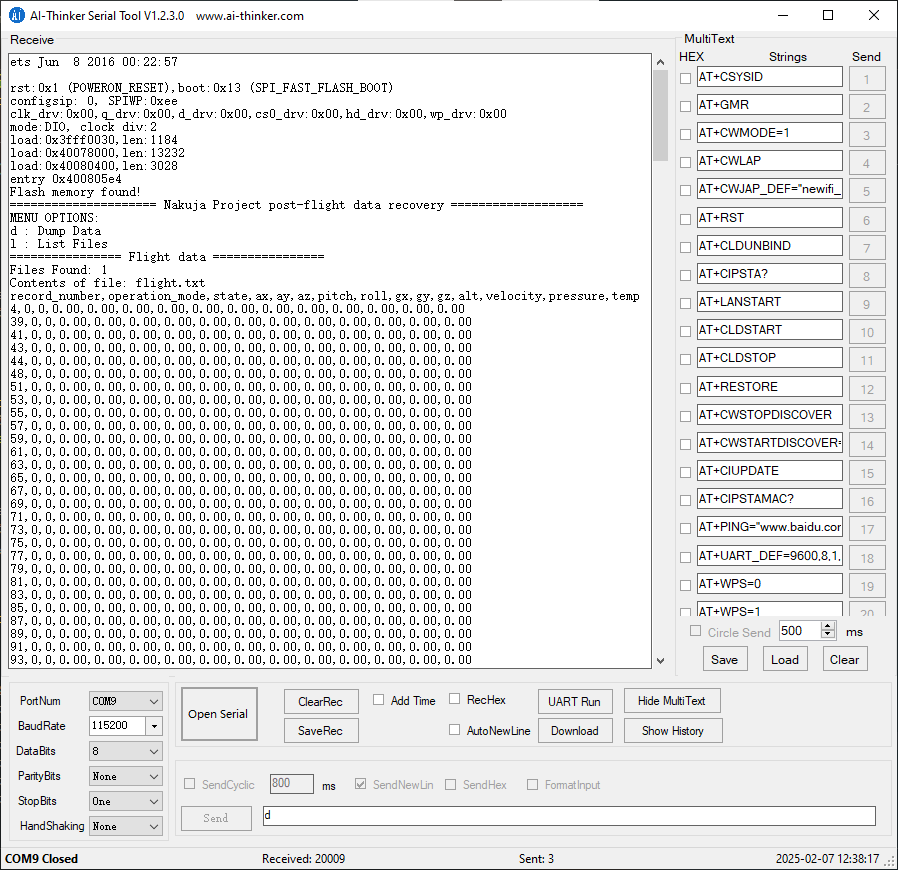
- To dump the data, enter d and press send. You should see the data being printed on the console as csv strings. The image below shows this step:
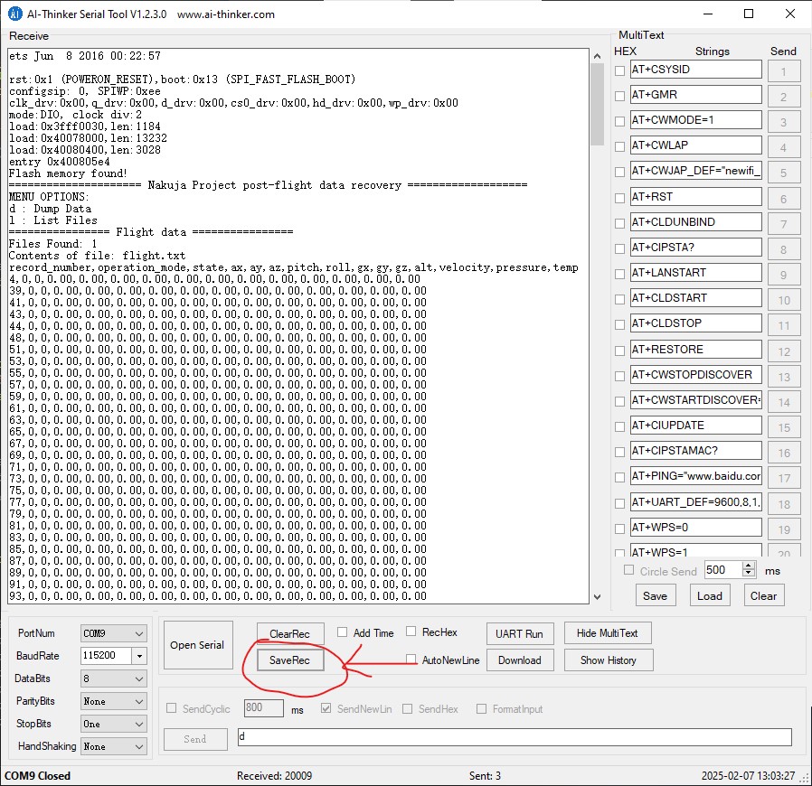
- Wait for the data dump operation to complete. After complete, press the Save rec file shown below and save the file as .txt
You should have your flight file recovered successfully.
If the onboard ESP32 has been damaged, use these steps:
Connect via USB cable and upload the code in \flight-data-recovery\n4-data-recovery-code folder, using the command below:
- Open AiThinker serial tool and dump the data into a text file as outlined in the steps above
Avionics Integration and Power-Up procedure
This section describes how the avionics is integrated into the rocket and how it is powered up.
Integration procedure
- Note
- In development
Power Up procedure
Once the flight computer is inserted into the body tube, the RBF pin must be inserted into the pre-allocated RBF hole on the body tube.
These next steps describe the sequence of events and observations made after the RBF pin is removed.
- Pull out the RBF pin
- The flight computer beeps once and goes through its boot-up sequence. If debugging this via the serial terminal, you should see a bunch of messages showing messages from the flight computer. If not seeing any messages, ensure the DEBUGGING and DEBUG_TO_TERMINAL in defs.h are set to 1.
- The green LED lights up and starts blinking to indicate the flight computer is in SAFE MODE.
- The flight computer creates an access point to allow for WIFI configuration. (see WIFI configuration section to see how to connect the flight computer to the network)
- Once the WIFI is connected successfully, the base station should start receiving the telemetry packet from the flight computer.
- If a telemetry packet is received from the base station, then the flight computer avionics is a GO!
Testing Procedures
To perform testing and integration of the flight computer, follow the steps below:
Hardware setup
- Referring to the N4 flight computer pinout, make sure the Test/Run toggle is set to TEST-MODE
- Upload the n4-flight-software code to the flight computer as per the instructions in the [Upload and run] section above
How to use the Nakuja Flight Computer Testing Engine
The testing engine is built to streamline the testing procedures and help inteprate the commands received from the Device Under Test during the testing phase. It also helps in downloading the test data to the Flight Computer for simulation.
Installation
- Note
- In development
Downloading the test data
- Double click on the app to open. The following window appears.
- Select the COM port that the flight computer is connected to.
- Select the baud rate
- Choose the test-data CSV file.
- Click Connect. The flight computer will be connected to the PC via serial. [Connected on COM[X] ] shows on the status bar.
- On the flight computer, press on the RESET/EN button and observe the serial Monitor. A code 21 should be received on the Serial Monitor every 4 seconds. Here is the X-MODEM commands list for quick reference:
X-MODEM Commands
| Command | HEX | DEC | Description |
| SOH | 01 | 1 | Start of Heading |
| ACK | 06 | 6 | Positive acknowledge |
| NAK | 15 | 21 | Negative acknowledge |
| CAN | 18 | 24 | Cancel |
| EOT | 04 | 4 | End of transmission |
- Click on Link Data. The test engine will download the test data to the flight computer, and the progress will be indicated on the serial Monitor
Contributors
Our thanks go to the following current and previous avionics team members for their contribution:
- Edwin Mwiti
- Junn Hope
- Jones Kisaka
- Ruth
- Safa Osman
- Tabby Achieng
- Sharlyn
- Pat
- Emmanuel Nindo
- Fortune
- Newton
- Rodney
- Sammy
- Michael Kimani
- George Bange
- Maisha
- Naomi Chesang
- Brian Munene
- Samson Onyambu
- Cate Kabura
- Amos Korir
- Graig Kipkorir
- Jerry Mumo
- Esther Mamai
- Martin Simbona
- Jeff Mboya
- Washington Kamadi
- Ian Muchiri
- Kibandi
- Emmanuel Obara
Victoria
Ad Astra!!